Group Technology Layout Adalah – Technology 2 Group technologies is a production technique and philosophy to increase production efficiency by “basic uniformity” forms of components, sizes, process routes, etc.
Group technology is aware that many problems are similar and that a grouping of such problems can be found to solve a set of problems, which is to save time and effort. (SOLAJA 73) The first book formalizes the concept: Mitrofanov, SP 1958, “Scientific Principles of Group Technology”
Group Technology Layout Adalah

6 Why group technology? Average reduction in dose size of part increases
Use Flink Hudi To Build A Streaming Data Lake Platform
The rapid distribution of the number and diversity of products that lead to a smaller dose size increases the demand for closer tolerances, leading to the need for economic means for increased material varieties, increasing the need for the total price of the product to increase labor efficiency. Increasing communication in production functions to minimize production costs and maximum maximum production.
The GT application provides a common database for effective CAD/CAM implementation, leading to a successful CIM implementation. The integration of the design, production and quality provides the structure and maintenance of information on the design and production, processes and production opportunities that the overall database plays a crucial role in the development and implementation of CAD/CAM.
GT codes reproduce data planning processes can change the process plan for an existing process process from a similar part. The above criteria enable automation production plans to automate their operations by organizing theoretical machines in cells. This cell production system is based on the GT concept
It is more than just a technique, but the overall philosophy of production. Engineering data for processing for processing for processes Inventory Inventory Inventory tools Engineering Planning assessment of purchasing industrial relations assembly for management management MFG quality. Engine Research and Accounting GT Delivery and Receiving Accounting
Differences Between Line Or Product Layout And Process Or Functional Layout.
The range of lathe milling l l m m d d d d d d a a a a a a a a a a a a a a a a a a a a a a a a a a a a a a a a a a a a a a a a a a a a a a a a a a a a a a a a a a a a a a a a a a a a
Three techniques for forming part of the families 1 .. Silent judgment or visual inspection may use photos or prints of component using subjective judgment 2. The production flow analysis uses the information contained in the route list (hence only MFG. Information), grouped according to the necessary treatment
Geometry/design codes and MFG. Information about components codes are alphanumeric chains, easier use for other analyzes

GT coding can benefit from many aspects of the company and fall into one of the 3 categories: 1. 3. Systems based on design and MFG.
Advantages Group Technology Layout Ppt Powerpoint Presentation Infographic Cpb
Examples: attributes of design part of the main outer shape of the MFG material part of the MFG. Attributes Basic processes small operating appliances required length/diameter Celery surface coatings
1. Code Monocode (or hierarchical structures) in which each digit increases the information given in the previous digit, difficult to construct, provides deep analysis, usually for permanent information, continuing information
32xx Hydraulic Electric 3231 3233 321x 323x Mechanical energy acceptance of transmission 322x 3232 without UNC fiber 3223 3222 3222
Each digit depends on all others, represents information that is independent of the previous ones, the codes are compact easy to use and develop suitable for computer analysis and lack details about Monocode Polycode more than monocodes more than monocodes
Universal Icon Symbols Group Of 16 Modern Flat Color Filled Lines Of Growth Analysis Sun Research Layout Editable Creative Vector Design Elements 17840672 Vector Art At Vecteezy
There are certain digits forming monocodes, but accumulate them together in the overall swallow arrangement, the best properties of Monocode and Polycode subgroups are formed by the fact that they are in the structure of Monocode, the hybrid code is compact from the attribute code is compact
33 Technique: 1. Determine the requirements of the Part and Machine 2. Do not necessarily code each part of the geometry of the part (and size) Additional specifications (tolerance, surface cover) 3. Large range) One and the same set of machine machines 4.
Steps from group technological applications (modified HAM442) Not all cost savings are instant … Improvements in engineering design materials and purchasing benefits in creating the benefits of manufacturing utilities and adjusting the benefits of the overall cost and benefits (month)

OPITZ Classification system – Miclass – DCLASS – KK – 3 – code system – camouflage system – analog system Part – coat system system RNC
Group Of 16 Flat Color Filled Lines Signs And Symbols For Layout Sell Tax Home Team Editable Creative Vector Design Elements 17872846 Vector Art At Vecteezy
Developed H. Opitz, University of Aachen, Germany Alpha -numeric symbols used to present various attributes digit sequence numbers: ABCD 12345 – Form code – design attributes ABCD attributes – secondary code – specific needs
This is also called a number of systems with very class – 12 to 30 digits. The first 12 codes are universal codes of another 18 codes are other codes
42 Miclass Encoding First 4 Digits Are Engaged in Shape, Basic Form, Elements of the Form and Position Next 4 – Dimensioned Information: Basic Dimension, Ratio of Different Sizes, Auxiliary Dimensions Digit 9 and 10 – Information on Tolerance Next 18 Digits : Dose size, time for piece, cost and operation data
43 MICLASS coding parts can be encoded using a computer interactively – the user answers a number of questions asked by computer – based on questions – computer assigns code, it is difficult to make adjustments if the code does not provide the necessary information
Dlt Technology Private Blockchain Technology Ppt Portfolio Layout Ideas Pdf
44 DCLASS DCLASS CODING SYSTEM – The design and classification system consists of 8 digits of the first segment – 3 digits – indicates the basic form of the second segment – 4. – 5th digit – state the total size of the coded part of the fourth segment – 6. The digits – represents the exact end segment – 7 and 8 digits – type of material – easy computer and therefore it is a commercial encoding system
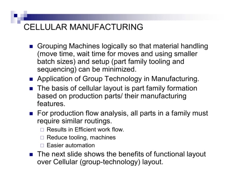
Access to partial creation of family and machine cells – introduced from parts of J. Bubridge, which is subject to common operations, are grouped into part of the families. Machines used to carry out these general operations can be grouped as a cell, so this technique can be used in the Factory Layout
Method for identifying families of parts and related groups of machines that are part of families are working parts with the same or similar routes used to create machine cells that PF uses more production data rather than designing data to identify the families that overcome two anomalies of parts.

The procedure for analyzing the production flow (PFA) consists of the following steps: data collection. The minimum data required in the analysis is the number of components and sequence of work obtained from the process plans. Sorting process processes. The sorting process is used to group parts with the same procedural plans. Scheme PFA. The processes used for each group are then displayed in the PFA diagram as shown below.
Time Nightclub Table Layout For Small Group?
4. SHL Analysis. The data model in the PFA diagram is identified and re -grouping related groups in the new model that combines groups with similar sequences of machines.
50 Advantages of PFA and PF DCAs use production data to identify families of parts of parts overcome two anomalies in classification and coding 1 anomalies: The main geometry is completely different, but also have the same processes of 2 anomalies: the geometry of the part is similar but requires different routes processes
51 PFA deficiencies do not provide any mechanism for rationalizing production routes, do not take into account the route sheet, whether the route sheet is optimal or consistent or logical final part, and the machine grouping can be under optimal, as the sequences of routes are prepared. Planning processes. Routes can contain processing steps that are non -optimal, illogical and unnecessary
This is to determine how to organize machines in the layout of storage equipment or in the physical location of the factory configuration of production facilities Configuration of departments, working centers and equipment at the destination of the transmission process, achieve economically required quantity and quality of production and quality
If You’re Still Not Leveraging Ai To Enhance Your Business Operations You’re Wrong! Ai Is The Future, And @microsoftcopilot Is Leading The Way. 🚀 As Your Trusted Technology Partner, Tbo Can Help
Layout planning is the solution to the best physical arrangement of all resources in devices with sources for devices can significantly affect the performance of two wide categories of operations: interrupted processing systems – low volume of many different products continuous processing – a large volume of several standardized products 53
Functional distribution or CPU – groups similar sources along with products or lines – designed to create a specific production efficiently group or hybrid distribution – combine the aspects of the process and product design – the product is two large; eg building 54
Sources are specialized devices are capital intensive processing rates are faster costs for cost processing are more requirements for low levels for storage space, lower flexibility is on the market low wiley 2010 55

Resources used are general -General devices are less capital intensive devices are more work -intensive sources have a higher flexibility percentage of processing are slower material processing costs are higher 59
A2. (a) A Manufacturing Factory Produces 9 Parts By Using 7 Machines As Shown In The
Step 1: Collection of information: Required space, available space, determine measures proximity Step 2: Elaborate alternative block plans: Use centers, including paths and stairs as drawings, 3-D models and


